
Overview:
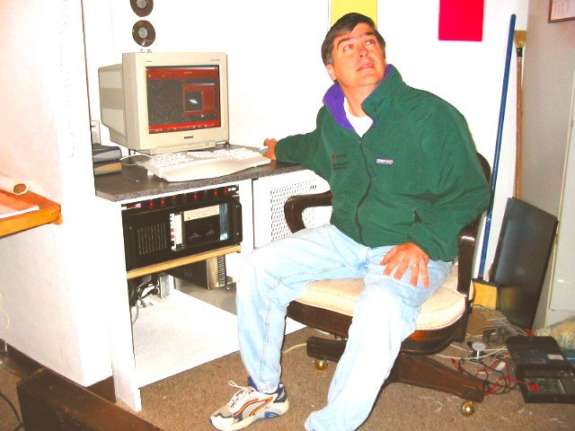
The heart of this telescope is its computer system. The computer runs 24/7 and is in constant contact via Satellite Internet connection to update this web site using ASP.NET Web Services with status and weather.
System:
The current system is 750Mhz AMD, 256Meg RAM, CDR, two 40 gig hard drives in RAID 5 configuration.
The motion base uses Compumotor PC-23 Indexer that drives two Compumotor AL microstepper drivers that drive stepper motors and the loop is closed using incremental encoders.
On each axis is mounted a Byers 24 inch worm gear.
History:
When this project began in 1980's, there were few computer controlled telescopes in world. Some university telescopes had computer control but, any amateur setup was a complete and utter kluge because of the price of the hardware. A few companies were beginning to offer telescopes in the 0.6 meter range but none offered anything resembling computer control.
This left LSO with not only a daunting learning curve but a research nightmare. Fortunately, a member discovered Helen Knudsen, Head Librarian at the Caltech Astrophysics Library. She provided research papers on this subject. One paper by Jon Straede and Patrick Wallace (1976) stood out, 'The AAT 3.9m Telescope: Software controlling slewing, setting, and tracking'.
What developed from this paper was the concept to breakdown the motion of the telescope into components. Moving the scope to counteract the rotation of the Earth, called Tracking, is but one component; slewing or moving the telescope from place to place is another. Then the sums of all were divided up into time slices.
Researching was one thing, finding components off the shelf in that era that wouldn't break the bank another. After many months a local motion sales technician started to work with us on the system. One of the components discovered was the PC-23 indexer from Compumotor. A major feature is it permits slices of time called streaming! In each 50ms time slice (interrupt) we calculate where the scope must be next, and this is then sent to the indexer card in the form of steps, yielding a tracking, moving, living, computer controlled scope!
Then member Jack Hudler designed the control system, and wrote all of the telescope control software using Microsoft Visual C++ and NuMega DriverWorks (for the NT device driver). In the current implementation the time slice interval is provided by a PC-TIO-10 Timer/IO card from National Instruments which is configured to interrupt the system every 50ms. The NT device driver processes that interrupt and sends the steps to the indexer. In the MSDOS implementation the system timer interrupt was reset to 50ms.
By today's standards the PC-23 is an antiquated indexer ISA PC card. The modern indexers have what are called blended moves, which would allow you to program the card to output the clock rate for earth's rotation and blend another move to an object on top of that. For the time being this card suffices to do the job until the next revision.
With our quality drive system it's only natural that we wanted it to do something besides track and move around with the hand-paddle... you want it to find objects for you. But first you must have coordinates for the object…that's easy today, just get some databases. When we started we had to call up NASA's Space Science Data Center and ask them to copy a bunch of astronomical databases on some large computer tapes. Being PC folks we were mystified when they handed us a 12-inch reel of tape. What to do with it? We finally managed to read it and copyied all the data onto floppies, a project none of us will soon forget. Today? Just go to the web site and download them.
Once you have a coordinate from a database you must do calculations to make it a useful, including corrections for proper motion, parallax, precession, nutation, annual aberration, light deflection, Earth rotation, diurnal aberration, and refraction. (this yields Mean to Observed place correction) And that's for starters! You slew the scope to the coordinates you calculated and voila!... no object. It's close though... just a little to the west there. After analysis you realize that the preceding calculations were just the beginning. There is flexure in the mount!
Well, as embarrassing as this sounds today for sophisticated scopes, we initially had a telescope with a 5 to 10 arcminutes of pointing error. In 1993 Jack was working on a Orthogonal Polynomial Surface fit algorithm by Jim Harwood that looked promising, but a job called him out of the area for a 6 years. Magically in 1995, LSO rediscovered Patrick Wallace ,the very person whose paper on telescope control started Jack’s computer control work. By this point he had developed TPOINT! With his assistance and software LSO refined his control software to compensate for all manner of mount flexure that all telescopes have – the bigger the scope the more flexure you have. TPOINT enabled us to find math errors in the software first, and then used Patrick's SLALIB, a positional astronomy library to replace the low precision methods for mean to observed place calculations. Thus a new set of calculations were added which yields the Mount Coordinates Position, or the location which takes into account all errors.
Patrick Wallace flew in to LSO one day and assisted Hudler in running some of the first tests on the system... wow did we find bugs in the mount. Slop here, slop there... primary mirror sloshing around... dec axis bearings with longitudinal run out... bad transmission on the HA axis (Dojen zero backlash transmission with periodic error a plenty and where 80% of the pointing error was!) and did I say slop. We tighten here and there; new bearings and gears all around and afterwards did a long TPOINT run of 200+ stars. When the run was processed through TPOINT, it revealed that the pointing error had fallen to 22 arcseconds! At last LSO had achieved their desired level of perfection.
Details:
For those that like numbers. The motors are driven by microsteppers which provide 25,000 steps per revolution. Each Byers worm gear has 572 teeth. To make a full 360 rotation of the telescope axes, the HA has 23,833,333 steps and 14,300,000 in DEC. That gives us the step resolution in HA of ~0.054 arcseconds per step, and ~0.090 for DEC. This resolution allows for very fine motion during guiding. The higher resolution in HA is due to the 80/48 reduction gears that came with the Byers HA worm block assembly.
 |
 |